In this tutorial we will check how to create a very simple alarm system with a buzzer and a PIR motion sensor. We will be using the Arduino core, running on the ESP32. The tests were performed using a DFRobot’s ESP32 module integrated in a ESP32 development board, and a DFRobot’s PIR sensor module.
Introduction
In this tutorial we will check how to create a very simple alarm system with a buzzer and a PIR motion sensor. We will be using the Arduino core, running on the ESP32.
Basically, when motion is detected by the PIR sensor, we will trigger the buzzer to start emitting a loud sound. When the sensor stops detecting motion, then we stop the buzzer.
We will leverage interrupts to avoid constantly polling the motion sensor, like we covered in this previous post. To achieve this, we will need to use some FreeRTOS functions, as we will see below in the code sections.
For a tutorial on how to control a buzzer with the ESP32, please check here. As explained in that post, at the time of writing, the higher level Arduino tone function is not yet implemented in the ESP32 Arduino core, so we will leverage the LED PWM functionalities of this microcontroller to control the buzzer.
In this tutorial we will use a DFRobot’s PIR sensor module, which already contains all the electronics we need to connect the sensor to a microcontroller and start using it. I’m also assuming the use of a ready to use buzzer module, which can be directly controlled from a digital pin of a microcontroller.
The tests were performed using a DFRobot’s ESP32 module integrated in a ESP32 development board.
Electric diagram
The schematic for this tutorial is very simple, as we will only need to connect a pin of the ESP32 to the buzzer and another to the PIR motion sensor. The schematic for this is illustrated below in figure 1.

Figure 1 – Electric diagram.
Both the buzzer and the PIR motion sensor can operate at 3.3 V, which facilitates the design of the circuit. Note that all the devices should have a common GND.
Although some ESP32 boards have a power supply pin to connect to other devices, many times the maximum current drawn that those pins can supply is not specified. Since we are already interacting with two modules, my recommendation is to use an external power supply such as this to supply the whole circuit.
As can be seen in figure 1, one of the ESP32 GPIOs will be connected to the PIR sensor, since this device outputs a voltage of 3.0 V when motion is detected. Note that although our circuit is operating at 3.3 V, a value of 3.0 V is still interpreted as a HIGH logical level by the ESP32, which means we can interact with the sensor considering it outputs a digital signal.
Regarding the connection of the ESP32 to the buzzer, we will also only need to connect a digital pin of the microcontroller, which will produce the square wave needed to make the buzzer emit a sound.
Global variables
To get started, we will first declare two variables to hold the number of the ESP32 pins connected to both the PIR motion sensor and the buzzer.
const byte sensorPin = 22;
const byte buzzerPin = 12;
Later, we will need to set some configurations regarding the waveform produced by the PWM hardware. We will also declare these configuration parameters as global variables.
First, we need specify the frequency, which will influence how the sound produced by the buzzer will be. I will use 2000 Hz, but you can test with other frequencies, as long as they are supported. You can read more about the supported frequencies here.
int freq = 2000;
Since the LED PWM hardware of the ESP32 supports 16 independent channels, with configurable duty cycles and wave periods [1], we also need to specify which channel we will be using. We will choose channel 0.
int channel = 0;
Finally, we need to set the resolution of the duty cycle and its actual value. Note that the accuracy of the duty cycle can be configured to a maximum of 16 bits of resolution [2].
Nonetheless, we will use a resolution of 8 bits since we don’t need that much granularity. This means that we can set the duty cycle between 0 and 255.
We will set the value of the duty cycle to have approximately 50% of the wave with a HIGH value and 50% with a LOW value, which should produce the louder sound [2][3]. Naturally, this corresponds to setting the duty cycle to half of what our resolution allows.
int resolution = 8;
int dutyCycle = 128;
Finally, we will declare a semaphore as a global variable, so we can implement an interrupt based approach for interacting with the PIR motion sensor. This needs to be a global variable so we can access it both in our Arduino main loop and on the Interrupt Service Routine.
SemaphoreHandle_t syncSemaphore;
Arduino Setup
Moving on to the setup function, we will start by opening a serial connection, to output some results from our program.
Serial.begin(115200);
Then, we will create the semaphore with a call to the xSemaphoreCreateBinary function. Since we are just going to perform synchronization between the interrupt handling function and the Arduino main loop, we only need a binary semaphore.
syncSemaphore = xSemaphoreCreateBinary();
Now, we need to set the pin connected to the sensor as an input pin, by calling the pinMode function. We pass as first input the number of the pin and as second the constant INPUT_PULLUP, so the pin is always in a known state (VCC), in case no signal is connected to it. This avoids having the pin floating between VCC and HIGH and generating interrupts wrongly.
pinMode(sensorPin, INPUT_PULLUP);
We will also need to attach the interrupt to that same sensor pin, so it triggers the execution of the handling function. Note that we want to know when motion is detected to start the buzzer (the sensor pin goes from LOW to HIGH), but also when motion is no longer detected, to stop the buzzer (the sensor pin goes from HIGH to LOW). So, in this case, we will want the ISR to be executed when the signal changes its value.
So, to attach the interrupt to the pin, we call the attachInterrupt function. As first input, we pass the result of calling the digitalPinToInterrupt function, which will convert the number of our pin to the corresponding internal interrupt number.
As second argument, we pass the function that will handle the interrupt event. We will call it handleInterrupt and specify it later.
As third argument, we need to specify when the interrupt will be triggered. We pass the constant CHANGE, since we want to detect a change in the digital signal level.
attachInterrupt(digitalPinToInterrupt(sensorPin), handleInterrupt, CHANGE);
To finalize the setup function, we need to setup the LED PWM. First, we need to call the ledcSetup function, passing as input the channel, the frequency and the resolution. Remember that we declared these variables globally.
ledcSetup(channel, freq, resolution);
We will also need to attach the channel we have just configured to the digital pin of the microcontroller where the PWM signal should be generated. In our case, it will be the pin connected to the buzzer.
To do this, we call the ledcAttachPin function, passing as first input the number of the pin and as second the number of the channel.
ledcAttachPin(buzzerPin, channel);
Arduino loop
Moving on to the main loop function, the first thing we do is trying to obtain the semaphore with a call to the xSemaphoreTake function. We pass as first input the previously initialized semaphore and as second the number of ticks to wait in case the semaphore has no units to take.
Since we want to block indefinitely until an interrupt occurs, then we pass the value portMAX_DELAY as second argument, which means that this task will wait blocked until the semaphore has a unit to be taken.
Note that, during the time this task is blocked, the FreeRTOS scheduler can assign the CPU execution to other task, which leads to a much more efficient code.
xSemaphoreTake(syncSemaphore, portMAX_DELAY);
When this semaphore receives a unit, then the task will unblock and we know an interrupt as occurred. Since our interrupt is triggered by a signal change (either from LOW to HIGH or HIGH to LOW), then we need to check the current value of the pin to know what happened.
We do this using the digitalRead function, which will return the current digital value of the pin (either HIGH or LOW, which corresponds to 1 and 0, respectively).
If the pin is currently HIGH, then motion is being detected. If it is LOW, then motion is no longer being detected.
if(digitalRead(sensorPin)){
  // motion detected
}else{
  // motion no longer detected
}
So, in case motion was detected, we need to call the ledcWrite function to specify the duty cycle and making the buzzer start emitting noise. So, we pass as first argument the channel number and as second argument the duty cycle of the wave (remember that we have declared it also as a global variable).
ledcWrite(channel, dutyCycle);
Otherwise, when motion stops being detected, we want to turn off the alarm, which means we should set the duty cycle to zero, so the output signal is constant and corresponds to GND, thus not producing any sound in the buzzer.
Note: At the time of writing, there is no function defined in the LEDC API to explicitly turn off the PWM functionality, so the best option seems to be setting the duty cycle to zero.
ledcWrite(channel, 0);
Interrupt service routine
To finalize, we will declare the Interrupt Service Routine. It will basically consist on giving a unit to the semaphore, in order to unblock the Arduino main loop to process the event.
We do this by calling the xSemaphoreGiveFromISR function, passing as first input the semaphore. As second input we will pass the value NULL, since we will not make use of the functionality offered by this second argument. You can check more about it here.
void IRAM_ATTR handleInterrupt() {
  xSemaphoreGiveFromISR(syncSemaphore, NULL);
}
The final code
The final source code can be seen below and it includes some extra prints for debugging.
const byte sensorPin = 22;
const byte buzzerPin = 12;

int freq = 2000;
int channel = 0;
int resolution = 8;
int dutyCycle = 128;

SemaphoreHandle_t syncSemaphore;

void IRAM_ATTR handleInterrupt() {
  xSemaphoreGiveFromISR(syncSemaphore, NULL);
}

void setup() {

  Serial.begin(115200);

  syncSemaphore = xSemaphoreCreateBinary();

  pinMode(sensorPin, INPUT_PULLUP);
  attachInterrupt(digitalPinToInterrupt(sensorPin), handleInterrupt, CHANGE);

  ledcSetup(channel, freq, resolution);
  ledcAttachPin(buzzerPin, channel);

}

void loop() {

    xSemaphoreTake(syncSemaphore, portMAX_DELAY);

    if(digitalRead(sensorPin)){

      Serial.println("Motion detected");
      ledcWrite(channel, dutyCycle);

    }else{

      Serial.println("Motion stoped");
      ledcWrite(channel, 0);

    }

}
Testing the code
To test the code, simply compile it and upload it to the ESP32 using the Arduino IDE, after all the wiring between the microcontroller and the devices is done.
Then, when the procedure finishes, open the Arduino IDE serial monitor. While you don’t move in front of the sensor, there should be no sound or messages printed to the monitor.
When you move, a motion detected message should be printed to the serial monitor and the buzzer should start producing sound. When you stop moving and motion is no longer detected, then a message indicating no more motion is detected should be printed and the buzzer should stop. The messages printed are shown in figure 2 below.
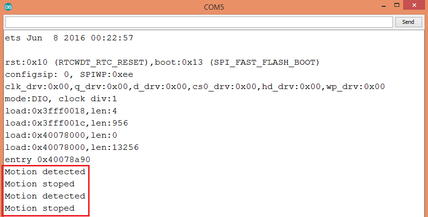
Figure 2 – Output of the program.
References
[1] https://www.espressif.com/sites/default/files/documentation/esp32_datasheet_en.pdf
[2] http://justanotherlanguage.org/content/tutorial_pwm2
[3] http://www.microchip.com/forums/m155649.aspx
I’m confused: pinMode(sensorPin, INPUT_PULLUP); Won’t this keep the sensorPin high regardless of what the PIR sensor data voltage is? Isn’t a pull down resistor needed on sensorPin?
I enjoy your turorials, if you could clarify this it would be appreciated. I noticed the same code on a previous tutorial and I’m missing something here.
Thanks!
Hi!
Thank you very much for the feedback 🙂
Regarding your question, the INPUT_PULLUP will only ensure that, when no signal is connected to your input pin, then it “forces” the input to be at a VCC voltage (which corresponds to HIGH). This means that it will be in a known state and you can rely on that when implementing your code.
This is needed because, if you have nothing connected to your pin and if you don’t set a PULLUP (or a PULLDOWN), then your pin will be in a state known as “floating”, which means it can fluctuate between the logical values 1 and 0.
This happens because of electrical noise, amongst other factors.
You can try to replicate this floating effect by setting up some pin change interrupt or continuously read the state of a digital pin declared just as input. To potentiate the effect, you can simply connect a jumper wire to the pin and leave, since it would act as “an antenna” and potentiate the effect of the noise. I never tried this on the ESP32 but I did experience the effect multiple times on Arduinos 🙂
Since we are relying on interrupts, then this fluctuation of signal between 0 and 1 would start triggering false events, which is not desirable since, in software, we would not have any way of deciding which events were false.
When you have a signal connected to your input pin, then this pull up doesn’t affect the circuit, so what defines if the pin is high or low is the input signal.
Note that this is just a precaution since you should start running the code only after the circuit is connected.
There are plenty of good resources that detail more the use of PULL resistors:
https://learn.sparkfun.com/tutorials/pull-up-resistors
https://www.electronics-tutorials.ws/logic/pull-up-resistor.html
Hope this clarifies 🙂
Best regards,
Nuno Santos
Hi, Thanks for the tutorial, im using the firebeetle esp32 with a vibration sensor and its working fine now. Im looking for a tutorial now on how to send this data (sensor activated/deactivated) to the smartphone via bluetooth.
Hi,
You’re welcome, I’m glad it is working 🙂
I don’t have any tutorial on the smartphone side, but I have some tutorials on how to get started with Bluetooth on the ESP32:
https://techtutorialsx.com/2018/03/09/esp32-arduino-serial-communication-over-bluetoth-hello-world/
https://techtutorialsx.com/2018/03/09/esp32-arduino-getting-the-bluetooth-device-address/
https://techtutorialsx.com/2018/03/13/esp32-arduino-bluetooth-over-serial-receiving-data/
Hope these help you getting in the right track 🙂
Best regards,
Nuno Santos
hey, did you find a solution please?
Hi, Thanks for the tutorial, im using the firebeetle esp32 with a vibration sensor and its working fine now. Im looking for a tutorial now on how to send this data (sensor activated/deactivated) to the smartphone via bluetooth.
Hi,
You’re welcome, I’m glad it is working 🙂
I don’t have any tutorial on the smartphone side, but I have some tutorials on how to get started with Bluetooth on the ESP32:
https://techtutorialsx.com/2018/03/09/esp32-arduino-serial-communication-over-bluetoth-hello-world/
https://techtutorialsx.com/2018/03/09/esp32-arduino-getting-the-bluetooth-device-address/
https://techtutorialsx.com/2018/03/13/esp32-arduino-bluetooth-over-serial-receiving-data/
Hope these help you getting in the right track 🙂
Best regards,
Nuno Santos
thank you for all. just a question please, how can I turn off the Buzzer and activate it using a Bluetooth device like my phone?
i have a error: Semaphore.h: No such file or directory