In this tutorial we will check how to control a relay remotely using serial communication over Bluetooth Classic. The tests of this ESP32 tutorial were performed using a DFRobot’s ESP-WROOM-32 device integrated in a ESP32 FireBeetle board and a DFRobot relay board.
Introduction
In this tutorial we will check how to control a relay remotely using serial communication over Bluetooth Classic.
For a guide on how to receive data on the ESP32 from a serial connection operating over Bluetooth, please check here. For a tutorial on how to control a relay with the ESP32 you can consult this guide.
The controlling logic we will employ in this tutorial will be very simple. Basically, if we receive a char with the value “1” we will turn on the relay and if we receive a char with a value of “0” we will turn it off. We are assuming the use of chars simply because it will be easier to test from a serial tool.
Note however that there are more robust ways of handling serial communication by building a simply byte oriented protocol on top of it, such as illustrated here.
The tests of this ESP32 tutorial were performed using a DFRobot’s ESP-WROOM-32 device integrated in a ESP32 FireBeetle board.
The electrical diagram
For this tutorial I’m assuming the use of a relay board which already contains all the electronics to be directly controlled with a pin of the ESP32. In my case, I’m using a DFRobot relay board.
The schematic for such solution is shown on figure 1. Note that depending on the relay board model you are using, you may be able to make it work with a power supply of 3.3 v or you may need to power it with 5 v. The one I’m using works fine with a power supply of 3.3 v.
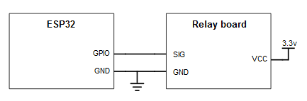
Figure 1 – Connection diagram between the ESP32 and the relay board.
I’ve generically labeled the control pin of the relay board as SIG, but depending on your device it may have a label or not. In case of the DFRobot relay board, the signal pin is the one connected to the green wire. The red wire corresponds to VCC and the black to GND.
Depending on your ESP32 board, it may be able to provide the power supply from a power pin. Nonetheless, if you are not sure, the best approach is to use an external power supply such as this.
Note that the controlling logic shown in this tutorial is independent of the hardware as long as it can be controlled by a digital pin. If you don’t have a relay you can use the same code to control a LED, for example.
The code
As we have seen in the previous serial over Bluetooth tutorials, the first thing we need to do is including the BluetoothSerial.h library, so we can use the serial over Bluetooth functionality.
#include "BluetoothSerial.h"
Next we will need an object of class BluetoothSerial. It will have the methods needed to both initialize the Bluetooth interface and to receive the data. The methods are similar to the ones available for the wired Serial class.
BluetoothSerial SerialBT;
We will declare an additional global variable to store the number of the digital pin that will be used to control the relay. I will be using pin 23, but you can test with others.
int relayPin = 23;
Moving to the Arduino setup function, we will start by opening a regular wired Serial connection, so we can output some debugging information.
Serial.begin(115200);
Next we will configure the digital pin as output. We do this by calling the pinMode function, passing as first input the pin number we have previously stored in a global variable and as second the OUTPUT constant.
pinMode(relayPin, OUTPUT);
Additionally, we will set the pin state to a low digital state, so we always know the relay state when the execution of the code starts.
This is done by calling the digitalWrite function, passing as input the pin number and the constant LOW.
digitalWrite(relayPin, LOW);
Next we will initialize the Bluetooth interface by calling the begin method on the BluetoothSerial object. Remember from previous tutorials that this method receives as input the name we want to assign to the device, which will be seen by other Bluetooth enabled devices when performing the discovery.
As output, it returns a Boolean value indicating if the initialization of the Bluetooth was successful or not. We will use this value for error checking.
if(!SerialBT.begin("ESP32")){
    Serial.println("An error occurred initializing Bluetooth");
}else{
    Serial.println("Bluetooth initialized");
}
Now that we have made all the initialization, we will start handling the received data om the Arduino main loop.
The first thing we will do is checking if there is data available. We can do it by calling the available method on the BluetoothSerial object. This method call will return the number of bytes available for reading, if there’s any, or -1 otherwise.
Since multiple bytes can be sent, we check for incoming bytes inside a while loop and read and process them one by one.
while(SerialBT.available()){
//handling code
}
If there is a byte available, we will read it using the read method of the BluetoothSerial object. Since, as mentioned in the introductory section, we are expecting to receive the commands as chars, we store the value returned in a variable of type char.
char command = SerialBT.read();
In order to facilitate the debugging of our program and to make sure we are actually receiving the data, we are going to print the received char to the wired serial interface.
Serial.println(command);
In order to encapsulate the logic to process the data, we will create a dedicated function that will receive the previously obtained char as input. We will define this function later.
processReceivedValue(command);
To finish the main loop function, we will do a small delay between each iteration. You can check the whole Arduino loop below.
void loop() {

  while(SerialBT.available()){

    char command = SerialBT.read();
    Serial.println(command);
    processReceivedValue(command);
  }

  delay(50);
}
The last thing we need to do is developing the function to handle the received char. We will assume that when the user sends a char with the value ‘0’ we should turn off the relay and if it has the value ‘1’ we should turn it on. In any other case, we do nothing.
So, on both valid cases, we use the digitalWrite function to either put the digital pin to a low or high state, respectively.
void processReceivedValue(char command){

  if(command == '1'){ digitalWrite(relayPin, HIGH); }
  else if(command == '0'){ digitalWrite(relayPin, LOW);}

   return;
}
You can check the final code below.
#include "BluetoothSerial.h"

BluetoothSerial SerialBT;
int relayPin = 23;

void processReceivedValue(char command){

  if(command == '1'){ digitalWrite(relayPin, HIGH); }
  else if(command == '0'){ digitalWrite(relayPin, LOW);}

   return;
}

void setup() {
  Serial.begin(115200);

  pinMode(relayPin, OUTPUT);
  digitalWrite(relayPin, LOW);

  if(!SerialBT.begin("ESP32")){
    Serial.println("An error occurred initializing Bluetooth");
  }else{
    Serial.println("Bluetooth initialized");
  }
}

void loop() {

  while(SerialBT.available()){

    char command = SerialBT.read();
    Serial.println(command);
    processReceivedValue(command);
  }

  delay(50);
}
Testing the code
After finishing all the electronics wiring, compile and upload the code to your ESP32 using the Arduino IDE.
Once the procedure finishes, open the serial monitor. You should get an output like figure 2, indicating a successful initialization of the Bluetooth interface.

Figure 2 – Successful Bluetooth initialization.
After this initialization, if you start a Bluetooth search with your computer, you should see the ESP32 as an available device. If you haven’t yet pared with it from following the previous tutorials, then perform the pairing.
When the pairing procedure finishes, you should have a new COM port available on your computer. On Windows 8, it is possible to check it on the Device Manager. If you need more help with this procedure, please check this previous post.
Now we need to establish a serial over Bluetooth connection with the ESP32. Note that the software we are going to use in the computer isn’t aware if we are establishing the communication over a regular wired serial interface or over Bluetooth, since the operating system will hide this implementation detail. This is a very good abstraction because it allows us to develop software that can work with both types of serial connections.
For this test I’m going to use Putty, a software that allows us to establish serial connections, amongst many other features that I really encourage you to explore.
I’m using Putty rather than simply launching another instance of the Arduino IDE and opening another serial monitor since I’ve experienced crashes in the past will establishing serial connections over Bluetooth with the Arduino IDE serial monitor. You can give it a try and check if the Serial monitor works reliably for you.
After opening putty, configure it like is shown in figure 3. As illustrated, we need to pick “Serial” option in the connection type. After that, you should put the COM port detected by your computer for the Serial over Bluetooth interface and choose a speed of 115200. Note that other speeds should also work.

Figure 3 – Putty configurations to establish the connection.
Once the configurations are finished, click the “Open” button. You can start sending commands to the ESP32 on the command line that will open.
By default, the characters will not be echoed back to the command line and will be immediately sent to the ESP32 after you type them. If you want a behavior more similar to the Arduino IDE serial monitor where we can type the characters and only send them after clicking the enter keyboard button, then check the configurations of figure 4. You need to set them before opening the actual connection with the ESP32.

Figure 4 – Changing Putty serial configurations.
As illustrated in the previous figure, you should access the Terminal tab and then choose “Force On” in the “Local echo” and “Local line editing” options.
Now, on the Putty command line, if you send a “1” the relay should be turned on and if you send a “0” it should be turned off. If you send any other character, it should simply be ignored and don’t affect the state of the relay.
You can check the Arduino IDE serial monitor again, which should be outputting the received characters, as shown in figure 5.

Figure 5 – Debugging output.
Related Posts
- ESP32 Arduino Serial over Bluetooth: Receiving data
- ESP32 Arduino: Getting the Bluetooth Device Address
- ESP32 Arduino: Serial communication over Bluetooth Hello World
- ESP32 Arduino Bluetooth: Finding the device with Python
- ESP32 Arduino Bluetooth Classic: Setting the device name
- ESP32 Arduino Bluetooth classic: Getting started
- ESP32 Bluetooth: Advertising a SPP service with SDP
- ESP32 Bluetooth: Receiving data through RFCOMM
- ESP32 Bluetooth: Finding the device with Python and BTStack
- ESP32 Bluetooth: Using the BTstack library
- ESP32 Arduino HTTP server: controlling a relay remotely
- ESP32 Arduino: Controlling a relay
Pingback: ESP32 Socket Server: Controlling a relay remotely | techtutorialsx
Pingback: ESP32 Socket Server: Controlling a relay remotely | techtutorialsx
Hello sir.. thank u for your great tutorial. May i ask you some question?
1. So in this way, we dont need to create such UUID service?
2. If i use this method, how about the energy consumption?
3. Can i use it with together with wifi withsome mqtt broker?
Thank u for your answer.
Hi!
Thank you very much for the feedback 🙂
1 – This pretty much works “out of the box”. You don’t need to create any service UUID to follow this tutorial.
2 – Unfortunately never had the chance to measure it. If you have the chance, let us know 🙂
3 – Theoretically you should be able to use both but, in practice, using both the Bluetooth and WiFi stacks will most likely occupy all your device’s resources, leaving no space to your application. I haven’t yet tried, but I’ve received some comments in the past indicating that. But it’s worth giving it a try.
Hope this helps 🙂
Best regards,
Nuno Santos
hello,
thanks for the tutorial it is really similar code as I did based on the bluetoothserial example on the arduino IDE, But I seethat the code you implement it is very nice¡:
if(!SerialBT.begin(“ESP32”)){
Serial.println(“An error occurred initializing Bluetooth”);
}else{
Serial.println(“Bluetooth initialized”);
}
on the same shoot you initialize the BT and inform if something wrong occurrs¡¡ (good implementation¡¡)
I’m trying to learn about how this library works but the information it is really poor… 😦
Do you know if we could configure a PIN access to pair the device?
if this option it is not posible any project from home autromation is not reachable due there is not security and someoneelse could acces to the devices….
what do tyou thikn about that? is there other way to control actuators using blootooth with a minimum security level?
thanks a lot¡
Hi!
Thank you very much for the feedback, I’m glad the code was useful 🙂
At the time I was more actively working with the Bluetooth, there was no way of setting a pin.
Supposedly, from this GitHub issue on the Arduino core, the availability of the pin feature depends on some lower level IDF functions which are not yet available:
https://github.com/espressif/arduino-esp32/issues/1458
Note that IDF is the ESP32 framework that the Arduino core uses under the hood.
So, I think it is a matter of waiting for these features to land on the Arduino core, most likely that issue will be updated when they are available.
Best regards,
Nuno Santos
Pingback: ESP32 Arduino Serial over Bluetooth: Client disconnection event – techtutorialsx
Pingback: ESP32 Arduino Serial over Bluetooth: Client disconnection event – techtutorialsx
Pingback: ESP32 Arduino Serial over Bluetooth: Get client address – techtutorialsx
Pingback: ESP32 Arduino Serial over Bluetooth: Get client address – techtutorialsx