The objective of this post is to explain how to test the AT commands firmware that comes pre-loaded in the WiFi Bee board, by using the Arduino IDE serial monitor.
Introduction
The objective of this post is to explain how to test the AT commands firmware that comes pre-loaded in the DFRobot WiFi Bee board, by using the Arduino IDE serial monitor. We will just check if the module is able to respond to our commands, print a list of available WiFi networks and print the version of the firmware.
You can also check more information about interacting with the WiFi Bee at the board’s ESP8266 Wiki.
The Hardware
As we saw in this previous post, the WiFi Bee board doesn’t have a USB header. So, we can’t directly connect it to a computer with a USB cable. So, we can interact with the board by using DFRobot’s Xbee USB adapter. This is the easiest method and the Wiki details how to start with AT commands using this adapter, as can be seen here.
Since I didn’t have one at hand at the time of writing, I used a more complex method for this tutorial, which was connecting the serial port pins of the module to a serial to USB converter. Just for those who are curious, I will leave here the steps needed.
So, first of all, since the ESP8266 operates at 3.3V and the WiFi Bee doesn’t do any voltage level conversion, we need to use a serial to USB converter that can operate at this level. I typically use this module, which allows to select between 3.3V and 5V using a jumper.
You can check the schematic at figure 1. Although the schematic is quite simple, doing the actual connections is not so easy since the WiFi Bee pins don’t have the standard breadboard spacing. So, it’s very hard to do the connections just by using female breadboard wires. Since I didn’t want to solder the pins of the board, it took me a while to have a stable connection, and that’s why I recommend using the previously mentioned Xbee USB converter.

Figure 1 – Diagram of the connection between the WiFi Bee and the serial to USB converter.
Figure 2 shows the pin mapping of the board. The picture was taken from the ESP8266 Wiki of the WiFi Bee.

Figure 2 – Pin mapping of the board. Taken from [1].
Note that we need to have the switch position in the BOOT side, the same way as indicated in figure 2.
Interacting with the board
We will interact with the board using the Arduino IDE serial monitor. This way, we don’t need to be coding an application to talk to the WiFi Bee. So, just open the Arduino IDE, select the COM port where the module is connected and open the Serial Monitor.
To talk to the module, we will need to use a baud rate of 115200 and select “Both NL e CR“, as indicated in figure 3. Note that NL corresponds to New Line and CR to Carriage Return [2].

Figure 3 – Serial monitor necessary configuration.
After opening the serial monitor and if the module starts correctly, it should output a “ready” message. If you don’t receive this message you can press the reset button on the board so it reinicializes. Figure 4 exemplifies the message sent by the module after booting / resetting.

Figure 4 – Ready message from the AT commands firmware.
The first command we will try is simply AT. This command allows a quick test to the AT commands functionality. This command takes no arguments and as output, we should only get an OK message, as indicated in figure 5. Note that I’ve sent the command twice in the example.

Figure 5 – Output of the AT command.
Now we are going to test some basic WiFi functionality. So, we will send the AT command that lists the available WiFi networks. The command to send is AT+CWLAP. As indicated in figure 6, the list is returned with the following information (by this order):
- Encryption type
- Network name (SSID)
- Signal Strength (RSSI)
- MAC Address
- Channel
Note that the encryption is returned as a numeric code. You can check the mapping in the AT Commands firmware document. In this case, 4 corresponds to WPA_WPA2_PSK.

Figure 6 – Output of the AT command to list the available WiFi networks.
We will also print the version of the firmware. To do so, we send the AT+GRM command. You should get an output similar to the one in figure 7.
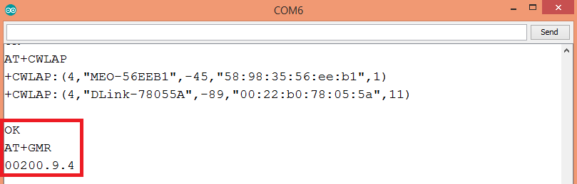
Figure 7 – Output of the AT command to print the firmware version.
To finish our tests, we will send a reset command. As indicated in figure 8, we need to send the AT+RST command. After receiving an OK answer, the module will reset and, after the procedure, it will return a ready message.

Figure 8 – Resetting the WiFi Bee with the AT+RST command.
Related content
References
[1] https://www.dfrobot.com/wiki/index.php/SKU:TEL0092_WiFi_Bee-ESP8266_Wirelss_module#AT_command
[2] https://arduino.stackexchange.com/questions/22852/what-does-serial-monitor-send-with-both-nl-cr
Pingback: ESP8266 WiFi Bee: Connecting to an Access Point with AT commands | techtutorialsx
Pingback: ESP8266 WiFi Bee: Connecting to an Access Point with AT commands | techtutorialsx
Reblogged this on DFRobot and commented:
helpful content~great!
Reblogged this on DFRobot and commented:
helpful content~great!
Pingback: ESP8266 WiFi Bee: Setting an Access Point with AT commands | techtutorialsx
Pingback: ESP8266 WiFi Bee: Setting an Access Point with AT commands | techtutorialsx
Pingback: ESP8266 WiFi Bee: Uploading Arduino programs | techtutorialsx
Pingback: ESP8266 WiFi Bee: Uploading Arduino programs | techtutorialsx