Introduction
This post explains how to upload code to ESP8266 using the Arduino IDE and a Serial-USB converter. We assume the use of an ESP-01 board, one of the cheapest and most used boards based on the device.
Hardware configuration
This tutorial assumes the use of the ESP-01 board, shown in figure 1, as the hardware. This is one of the most used boards based on the ESP8266 and can be bought for about 2 euros. If you are using another board (for example, a NodeMCU, which already has a USB connection) you can jump to the next section, which explains how to enable the ESP8266 support on the Arduino IDE.
![ESP-01 board. Taken from [1].](https://i0.wp.com/techtutorialsx.com/wp-content/uploads/2016/02/wifi_esp8266_esp01.jpg?resize=350%2C350&ssl=1)
In order to allow uploading code to the device, we need to guarantee that the ESP8266 starts in flashing mode. To do so, we need to connect its GPIO0 pin to GND before powering it, as shown in figure 2.

Then, we will need a Serial-USB converter to connect the ESP board to a computer. To do so, we connect the Rx and Tx pins of the board to the converter, as shown in figure 3. Besides that, the CH_PD pin should also be connected to VCC.

Important: The ESP8266 is a 3.3 V device. The schematic shown in figure 3 was done under the assumption that the Serial-USB converter works with 3.3 V voltage levels. Applying 5 V levels to the UART of the ESP8266 will damage the device. A good and versatile Serial-USB converter, which allows to change between 3.3 V and 5 V levels using a jumper, can be bought for less that 2 euros.
Since the ESP-01 is not breadboard friendly, it’s a good ideia to create a simple programmer to make the process of uploading code easier. This can be done using a perf board and some female connectors. There are also some adapters to buy here.
Arduino IDE configuration
The easiest way to configure the whole setup is to follow the guide provided here, which uses the boards manager of the Arduino IDE. As explained, we first need to install version 1.6.5 of the Arduino IDE (or greater), which can be found in Arduino’s repository of software.
Note: If we have another version of the Arduino IDE installed before and uninstall it to install version 1.6.5, an error such as “error opening file for writing: C\program Files (x86)\Arduino\java\bin\awt.dll” may occur. The solution is just simply restarting the computer.
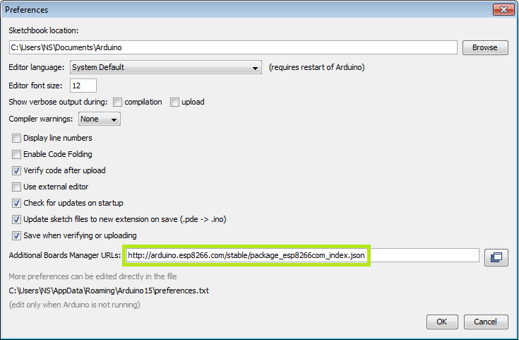
After the installation, we need to open the Arduino IDE and access the preferences menu, as shown in figure 4.

In the preferences menu, we need to add the following link to the Additional Boards Manager URLs field: http://arduino.esp8266.com/stable/package_esp8266com_index.json. This is shown in figure 5.
After that configuration, we need to do the installation of the ESP platform. To do so, we access the Boards Manager menu, as shown in figure 6.

On the Boards Menu manager, we search for the keyword “ESP” and the corresponding package will appear. Then we just click install, as shown in figure 7.

Once the installation completes, we need to select the correct board options for the ESP-01 board. In the board type, in the tools tab, we choose “Generic ESP8266 Board”, as shown in figure 8.

In the programmer entry of the same tab, we choose “esptool”, as shown in figure 9.

Finally, we can start writing code. After finishing, we just press the upload button (same as we would do for a regular Arduino board) and it starts uploading. Figure 10 shows the result of a successful upload in the command window.

It’s important to note that after the code is uploaded, the device will start to run it. So, if we want to upload a new program, wee need to reset the power of the device, in order to guarantee that it enters flashing mode again.
First program
Since this platform is based on Arduino, we can use many of the usual functions. As an example for the first program, the code bellow starts the Serial port and prints “hello from ESP8266” every second.
void setup() {

  Serial.begin(115200);

}

void loop() {

  delay(1000);
  Serial.println("hello from ESP8266");

}
If everything is working fine, we will see the output in the serial console shown in figure 11.

Now, we can start writing our IoT programs!
Suggested ESP8266 readings
References
[1] http://maker-marketplace.com/hk/wireless_communication/wifi/
Great! Thank you it works!
Hi!
You’re welcome, I’m glad it is working for you 🙂
Best regards,
Nuno Santos
Great! Thank you it works!
Hi!
You’re welcome, I’m glad it is working for you 🙂
Best regards,
Nuno Santos
Steffen what was the solution?
you need to hook the vcc and gnd to the power on Serial-USB … this is the problem, the diagram forgot to mention this
Steffen what was the solution?
you need to hook the vcc and gnd to the power on Serial-USB … this is the problem, the diagram forgot to mention this
my problem is that i get this error
warning: espcomm_sync failed
error: espcomm_open failed
error: espcomm_upload_mem failed
Hi!
Which board are you using? The ESP-01?
Those are very tricky because we need to get the uploading hardware right.
Here is a list of some troubleshooting possibilities:
https://github.com/esp8266/Arduino/blob/master/doc/faq/a01-espcomm_sync-failed.rst
Hope this helps.
Best regards,
Nuno Santos
you need to hook the vcc and gnd to the power on Serial-USB … this is the problem, the diagram forgot to mention this
hi I have some project but I’ve got the problem uploading my keypad+lcd program to the Generic esp8266 board. my keypad+lcd doesnt work with the new program. what should i do. thank you
Hi!
But did it work before?
Is it a code related problem or a hardware related problem?
Best regards,
Nuno Santos
hi I have some project but I’ve got the problem uploading my keypad+lcd program to the Generic esp8266 board. my keypad+lcd doesnt work with the new program. what should i do. thank you
Hi!
But did it work before?
Is it a code related problem or a hardware related problem?
Best regards,
Nuno Santos
esptool option is not showing